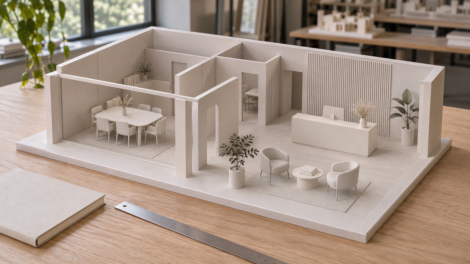
Illustrative concept image shown above; not a dimensional verification record.
A model can match the floor plan at first glance and still be wrong where the presentation matters most.
An opening may be measured to the wrong reference. A ceiling may use an assumed height. A wall may follow an outdated drawing while the furniture follows the latest revision. Once lighting and materials are added, those differences can become harder to notice—and easier to mistake for approved design.
CAD to 3D architectural modeling is therefore more than turning lines into walls. It is a translation process that needs a clear source, measurable checks and a visible boundary between confirmed information and interpretation.
For architects, developers and interior design teams, the useful question is not only how quickly a model can be built. It is how the team knows what it can trust before final imagery is produced.
Importing a drawing is not the same as verifying a model
A successful file import proves that information has entered the scene. It does not prove that the information has been interpreted correctly.
CAD linework can include several kinds of information in the same area: existing construction, proposed work, overhead features, annotations, furniture symbols and references from other drawings. A line’s presence alone does not establish its role in the 3D model.
Even a clean plan does not necessarily provide everything needed for a complete interior. Heights, opening details, level changes and ceiling relationships may depend on elevations, sections, schedules or a decision that has not yet been issued.
My professional priority is to establish which information controls the model before making it look complete. A clearly identified unresolved item is safer than a polished assumption that nobody realises they are approving.
What reliable CAD to 3D architectural modeling needs to establish
The team needs a shared definition of “accurate enough for this purpose.” A concept massing model and a detailed interior presentation have different requirements. Neither should be described as construction-verified simply because it looks convincing.
Before production develops, establish:
| Control | What it should make clear |
|---|---|
| Source baseline | Which drawing files, issue dates and revisions are being used |
| Scale | How source-file units relate to the 3D scene and measured results |
| Reference convention | Whether a critical measurement refers to a centreline, structural face, finished face or opening |
| Vertical information | Which levels, sections or elevations establish heights |
| Open questions | What remains assumed, conflicting or subject to confirmation |
These controls do not require the client to inspect modeling techniques. They allow the project team to review the result against an agreed basis.
Confirm scale with measurements, not appearance
A room that looks plausible is not a reliable scale check. A unit mismatch can affect the whole scene while camera framing makes the result appear reasonable.
Autodesk’s official DWG/DXF import documentation describes how incoming drawing units and 3ds Max system units are used when rescaling imported geometry.
Its Units Setup documentation also distinguishes display units from system units: changing the measurement display is not the same as establishing the geometry’s actual scale.
The practical implication is to confirm the import against known dimensions. Use checks that represent the project: overall extents, a dimension along another axis and relevant local features. Verify vertical dimensions separately when that information is available.
One matching measurement does not establish that every component is correct. A repeated block, a separately supplied asset or a modeled opening may still have a different issue.
Where a written dimension conflicts with the drawn geometry, record the discrepancy and ask the responsible design team which information governs. Do not silently stretch the model until one view looks right.
Check what the dimension actually refers to
Two measurements can use the same unit and still describe different things.
A nominal door size may not be the same as the structural opening or the clear passage. A room dimension may refer to finished faces while the imported lines describe the structure. A partition may carry finishes that are not represented by its simplest plan outline.
For visualization, these distinctions matter wherever they affect the visible result or the decision being reviewed. They can change the apparent proportions of joinery, openings, corridors and furniture arrangements.
The visualizer should not invent the technical answer. The useful professional contribution is to identify the ambiguity, explain its visual consequence and obtain a clear direction before refining dependent work.
This is a central discipline in CAD to 3D architectural modeling: matching a number is only meaningful when the reference points are understood.
A floor plan cannot confirm every height
Extruding a plan produces volume, but it does not establish the intended vertical design.
Ceiling height, bulkhead depth, window head levels, door heights and floor transitions need their own evidence. A model can be correct in plan yet communicate an entirely different spatial experience because one of those values has been assumed.
Prioritise the vertical relationships visible in the agreed cameras. For example, the relationship between a reception feature and its ceiling may be central to approval, while an unseen service area may only need the level of definition agreed for the presentation.
Modeling priorities can follow the image scope. The accuracy of visible design information should not depend on whether an error is easy to hide with a camera.
Review geometry before atmosphere makes it persuasive
Simple model views can make proportions, intersections and missing elements easier to discuss without the distraction of final finishes. They should be paired with measurements where dimensions matter; a clay render is not a dimensional certificate.
An early review should answer specific questions:
- Does the model follow the agreed drawing revision?
- Are the critical walls, openings, levels and heights checked?
- Are important conflicts still visible in the review notes?
- Are furnishings correctly sized for the approved selections?
- Has anyone changed the design purely to improve the image?
Consider a hypothetical reception scene. The desk may look elegant in perspective, but the opening behind it conflicts with the latest elevation. Correcting that relationship before material and lighting approval protects several dependent decisions at once.
The value is not merely finding an error. It is finding it at a stage when the team can respond clearly.
The interior visualization work and preparation process provides context for how drawings, model preparation and presentation requirements relate to the final imagery.
Automation needs boundaries and observable checks
Scripts, AI-assisted tools and direct software automation can support repetitive preparation and model creation. Their usefulness should be assessed by the reliability of the result, not by whether the process appears autonomous.
A repeatable action is not necessarily a correct action. A tool can consistently extrude the wrong outline or apply an unconfirmed height to every room.
Useful automation should therefore make its scope and assumptions understandable. The team should know which source it used, which elements it changed and which conditions caused it to stop for review. Unclear linework should not be converted into confident geometry without an opportunity to check it.
For a production team, the stronger benchmark is whether the workflow makes mistakes easier to detect and revisions easier to control. A visually complete model produced quickly is not a saving if its unrecorded assumptions later need to be untangled.
This is a quality-management principle, not a claim that any particular automation tool guarantees dimensional accuracy.
Preserve the source trail when the design changes
Once a model has been reviewed, a new drawing issue can invalidate part of that approval. Keeping the same file name or a similar-looking camera does not mean the underlying information is unchanged.
Record the new source revision, identify the affected geometry and recheck the related views. If the change alters a circulation route, opening or ceiling relationship, previously approved compositions or furniture positions may need another review.
Do not silently mix drawing issues into a single apparently final scene. Where the design team intentionally combines information from different issues, retain that instruction as part of the model’s basis.
This makes later conversations more useful: the team can distinguish a modeling correction from a design revision and understand why a new check is necessary.
The professional value is knowing what has been verified
For clients and employers evaluating a visualizer, ask for more than a demonstration of fast modeling. Ask how source conflicts are handled, how critical measurements are checked and how changes remain traceable.
My view is that CAD to 3D architectural modeling becomes dependable when confirmed geometry, approved interpretation and unresolved information remain distinguishable throughout production.
A visualization model can support design communication without replacing architectural, engineering or site verification. That boundary should remain explicit even when the images are highly photorealistic.
When reviewing your next model, ask: which important relationships have been checked—and what evidence supports that confidence?